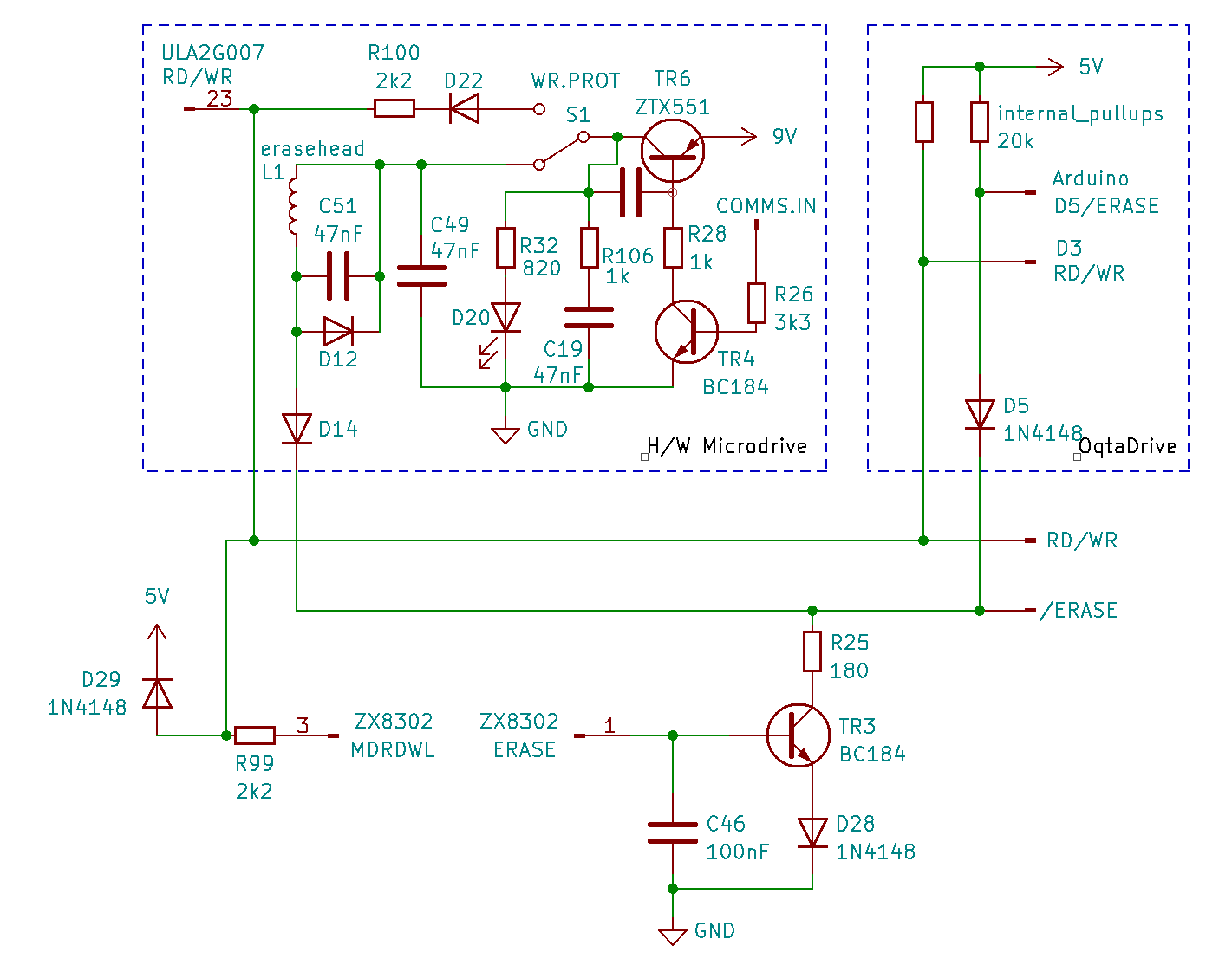
The QL has a few interesting design flaws, quirks, and factory faults. A rather obscure one is a problem with the write protection circuit. While on the Spectrum, Microdrives signal a writable cartridge to the Interface 1 by asserting 9V on the WR.PR line of the Microdrive bus (and don’t assert anything for a write protected cartridge), write protection on the QL is handled completely within each Microdrive unit. Here’s an excerpt from the QL schematics showing the write protection part:

Writing
First let’s look at what happens when the QL writes to a cartridge:
-
The
/ERASEline is pulled low. In the currently active drive, this allows a current to flow through the erase head coilL1, which is supplied viaTR6from the 9V supply. The tape is now being erased. -
The
RD/WRline is pulled low, switching the Microdrive ULA to write mode. This turns theDATApins into inputs and enables the write amplifiers. The data received via theDATAlines is now being written to the tape.
Write Protection
Now let’s see how this can be prevented. If the cartridge in the active drive has its write protection tab broken off, switch S1 goes into the WR.PROT position, causing two things to happen:
-
The erase head coil no longer receives its supply voltage. This obviously prevents erasure of the tape.
-
9V are fed into the
RD/WRinput of the ULA (pin 23) viaD22andR100(due toD29the voltage is limited to 5V). This effectively overrides a LowRD/WRline to High. The ULA consequently remains in read mode and does not activate the write amplifiers. The tape will not be altered.
What Could Possibly Go Wrong…
This works really well, as long as all components are present as shown in the schematic. Unfortunately, that’s not the case in all QLs. The trouble spot here is D22. This diode is located on the drive PCB. The designation D22 applies to drive 1 on an Issue 5 QL, for drive two it’s D23, and on Issue 6 QLs it’s D31 and D30, respectively (yeah, that’s right, backwards…). Now to the problems:
-
In Issue 5 QLs,
D22andD23are often missing. Write protection still works, but an inactive drive with a write protected or no cartridge places a load on theRD/WRline (R100,R32,D20,R106,C19). This may interfere with the communication between QL and an active Microdrive. The QL service manual therefore lists the addition ofD22andD23as mandatory modifications in section 1.3. -
In Issue 6 QLs,
D31andD30are sometimes (or always?) placed in the wrong direction. This for one thing leads to the same problem as a missing diode, i.e. load placed on theRD/WRline. But it also defeats the write protection! A Low on theRD/WRline is no longer overridden, so the drive ULA will happily write to tape. There doesn’t seem to be a mandatory modification note for this one in any service manual… Maybe by the time this fault was introduced, people weren’t really using the Microdrives any longer, and it largely went unnoticed.
The Fix
For use with OqtaDrive, the interference with the RD/WR signal is most relevant. A clear indicator of this problem are errors during format, sometimes format may not work at all, and overall flaky behavior may be observed. A quick way to check whether your QL suffers from this fault is to place cartridges with protection tabs present in all hardware drives and see whether that improves the situation. At the same time, this is also a simple workaround, if you do not want to open up your QL. For a permanent solution, it’s however best to add/correct the missing or incorrectly installed diodes. Alternatively, you can try adding a diode into the R/W line, with anode connected to the Arduino pin. This may solve the problem, but hasn’t been confirmed yet. If you try this, let me know of the results.
 OqtaDrive