
Before building OqtaDrive yourself, please carefully read the hardware section at the project home! It contains important instructions & notes. Not following these may break your vintage machine and/or the Arduino! However, bear in mind that all the information here and at the project home is published in good faith and for general information purpose only. I do not make any warranties about the completeness, reliability, and accuracy of this information. Any action you take upon the information you find here, is strictly at your own risk. I will not be liable for any losses and/or damages in connection with the use of OqtaDrive.
If you just want to try out OqtaDrive, you can simply build the adapter on a breadboard, following the schematics. The circuit is not very complicated and can be set up quickly.
If you rather want to build a proper device for continued use with your Spectrum and QL, there are several PCBs and 3D print models of cases for different configurations from which you can choose. Clicking on the PCB images or photos below will take you the respective resources on PCBWay, Thingiverse, GitHub, or wherever the corresponding artifacts are maintained. Linked images are indicated with the 🔗 mark.
Standalone for Spectrum and QL
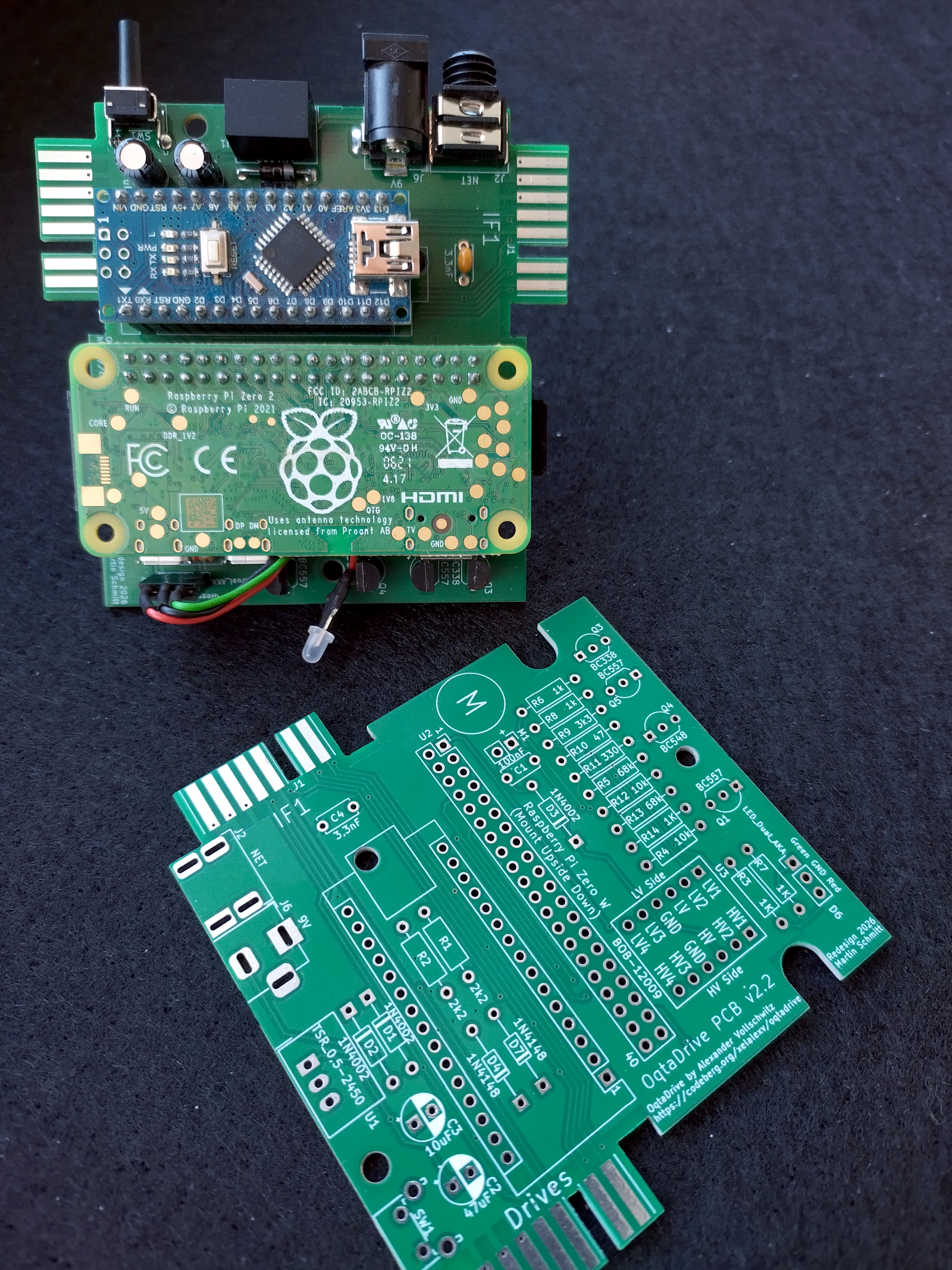
This is the fully fledged, complete solution including a RaspberryPi Zero W (1 or 2) or BananaPi M2 Zero, for running the daemon. Great choice if you want a self contained setup you can use with your Spectrum and/or QL, away from your PC or Mac. A 3D print model for a case is available as well. The PCB however also fits into the original Microdrive case.
It is available in two versions –V2.0 and V2.2– created by Martin S. from the tlienhard forum. Both versions were derived from Tom Dalby’s original PCB. They now include support for the Sinclair network functionality, a boost circuit for the write protect line (Spectrum only), and a shutdown button. The two versions only differ in the purpose of the second Microdrive connector (details below).
These PCBs have been thoroughly tested and are now the default option for a standalone OqtaDrive. So when building one, it is highly recommended to use this PCB, rather than any of the older versions. You can download the Gerbers by clicking on the respective image. Please note that they are not to be used for commercial purposes!
Cost: Based on prices for parts at commercial sellers in Germany from early 2026, it should be possible to build this standalone version with all features for roughly 40 Euros.
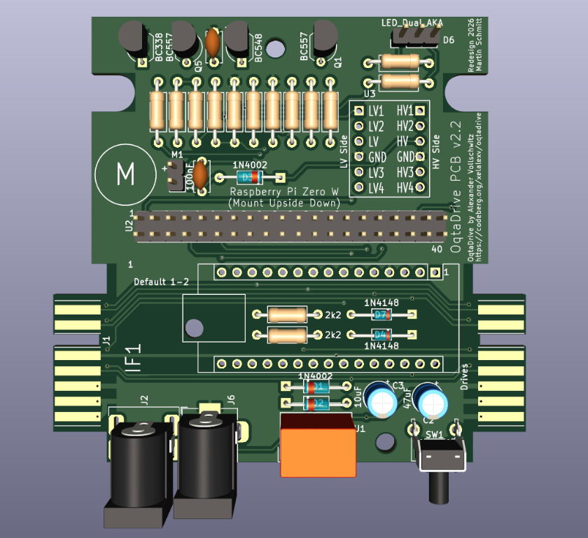
Version 2.2
This is mainly meant for use with a Spectrum and real h/w Microdrives. The Microdrive edge connector labelled IF1 is connected to the Interface 1, real h/w drives can be connected to Drives. You can still use this with a QL via the IF1 connector. The front of the unit would just be facing away from you. (Note that the network socket is not rendered correctly in the drawing below. See the photo at the top of this page for a fully built unit.)
🔗
|
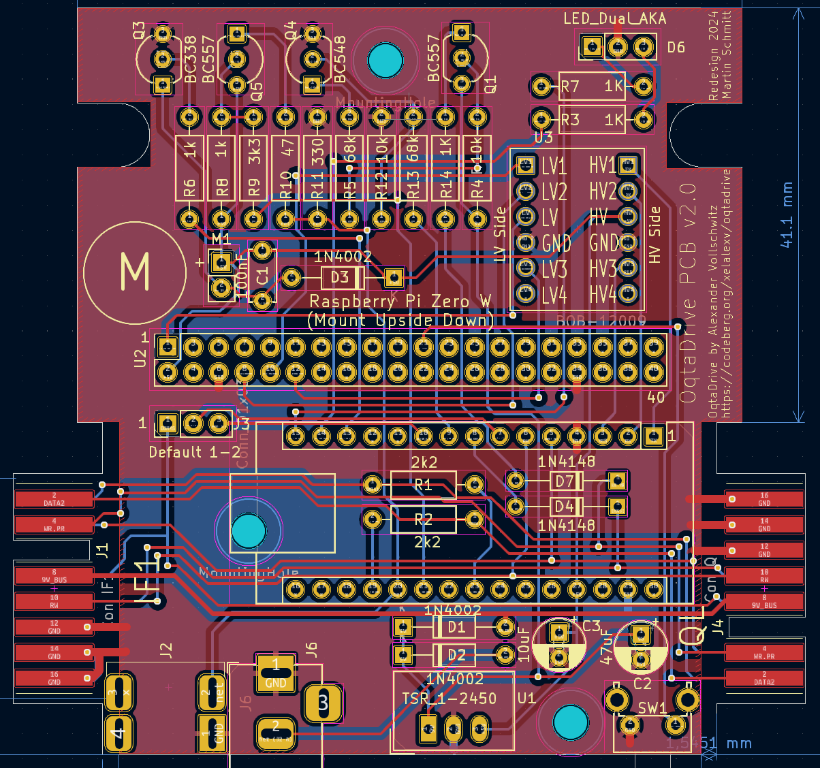
Version 2.0
Important: Even though this PCB has two Microdrive edge connectors, it is not possible to connect a real h/w Microdrive to the one that is not in use! This would require a special cable and a minor modification to the PCB. The two connectors merely allow you to place the unit to the left of a Spectrum and to the right of a QL, while its front is still facing you. If you want to connect real h/w drives, use version 2.2 of this PCB.
🔗
|
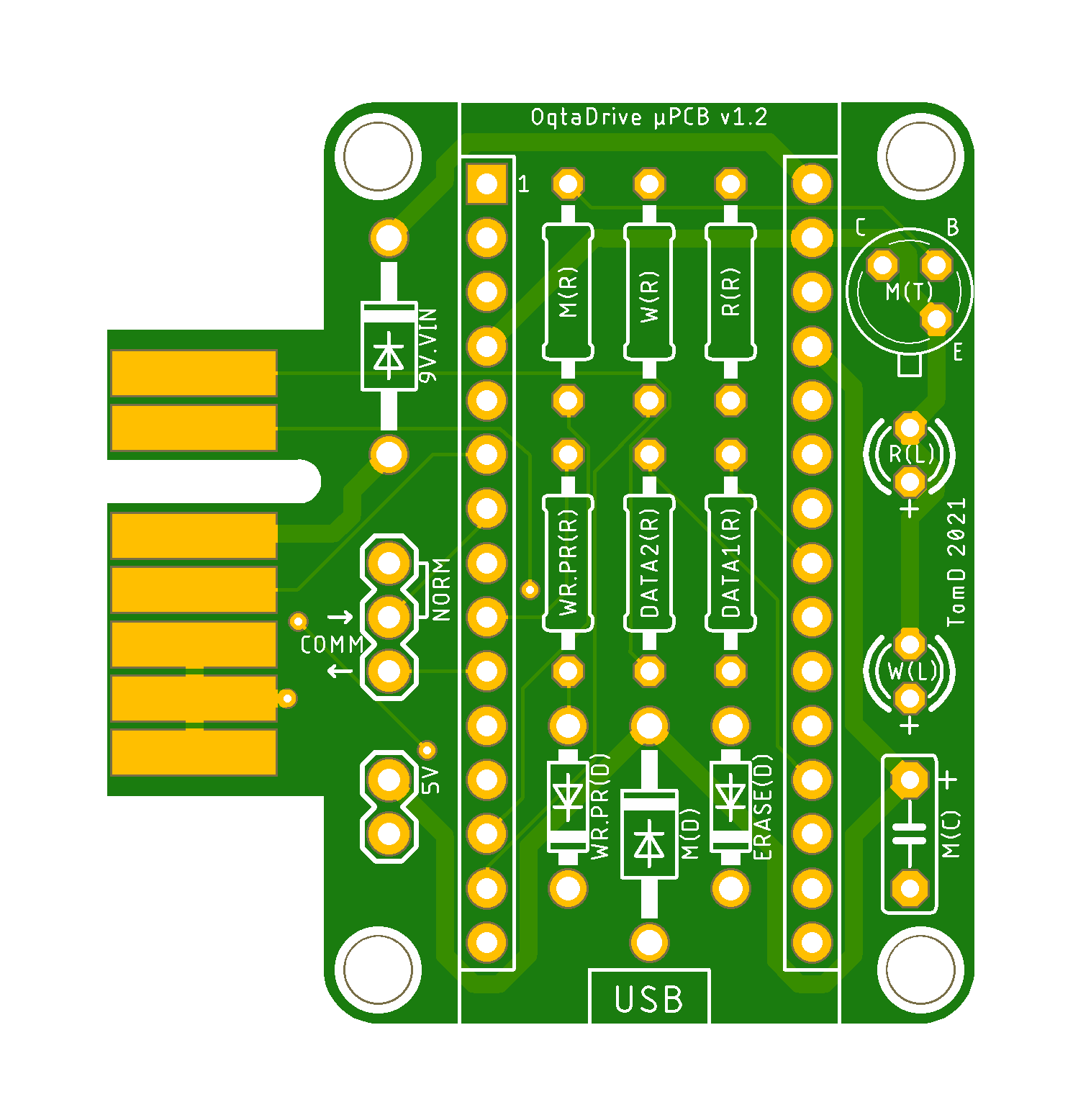
Micro
This is the smallest member of the OqtaDrive PCB family created by Tom. If you’re planning on running the daemon on your PC or Mac, and want the smallest possible adapter, this is the one. It works with Spectrum and QL. Tom also created a 3D print model for a case.
🔗
|
🔗
|
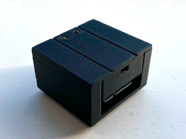
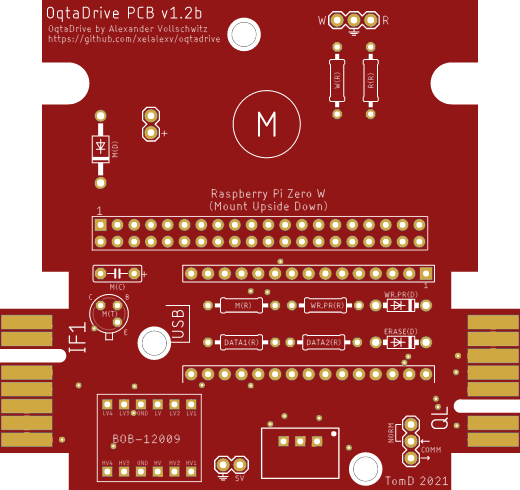
Deprecated - Standalone Version 1.2b
The original standalone PCB by Tom Dalby. This does not include the network port. Please consider using versions 2.0 and higher. Support for this board may be dropped in the future.
🔗
|
🔗
|
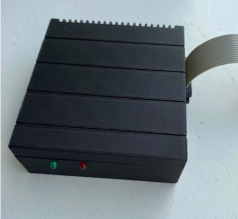
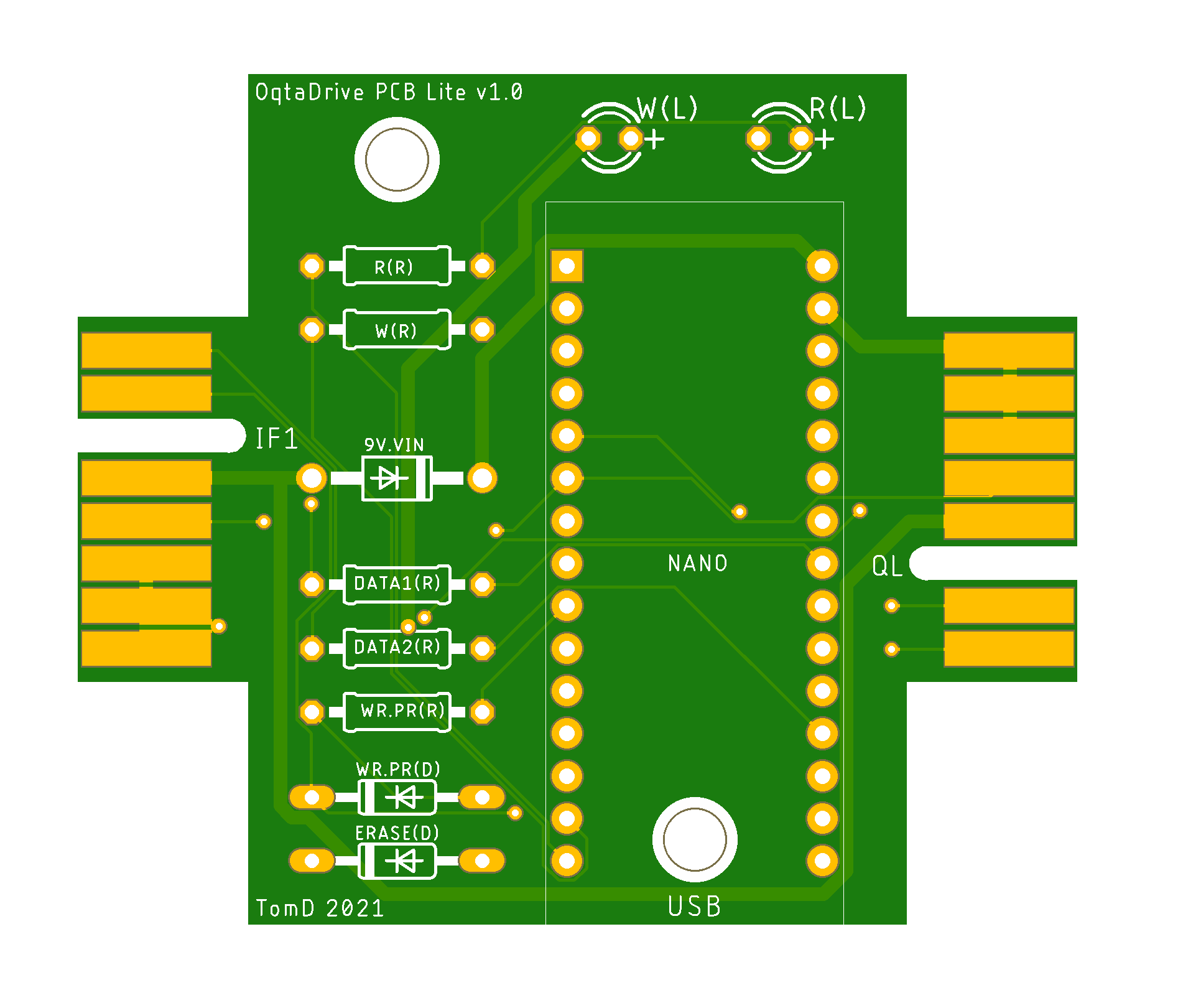
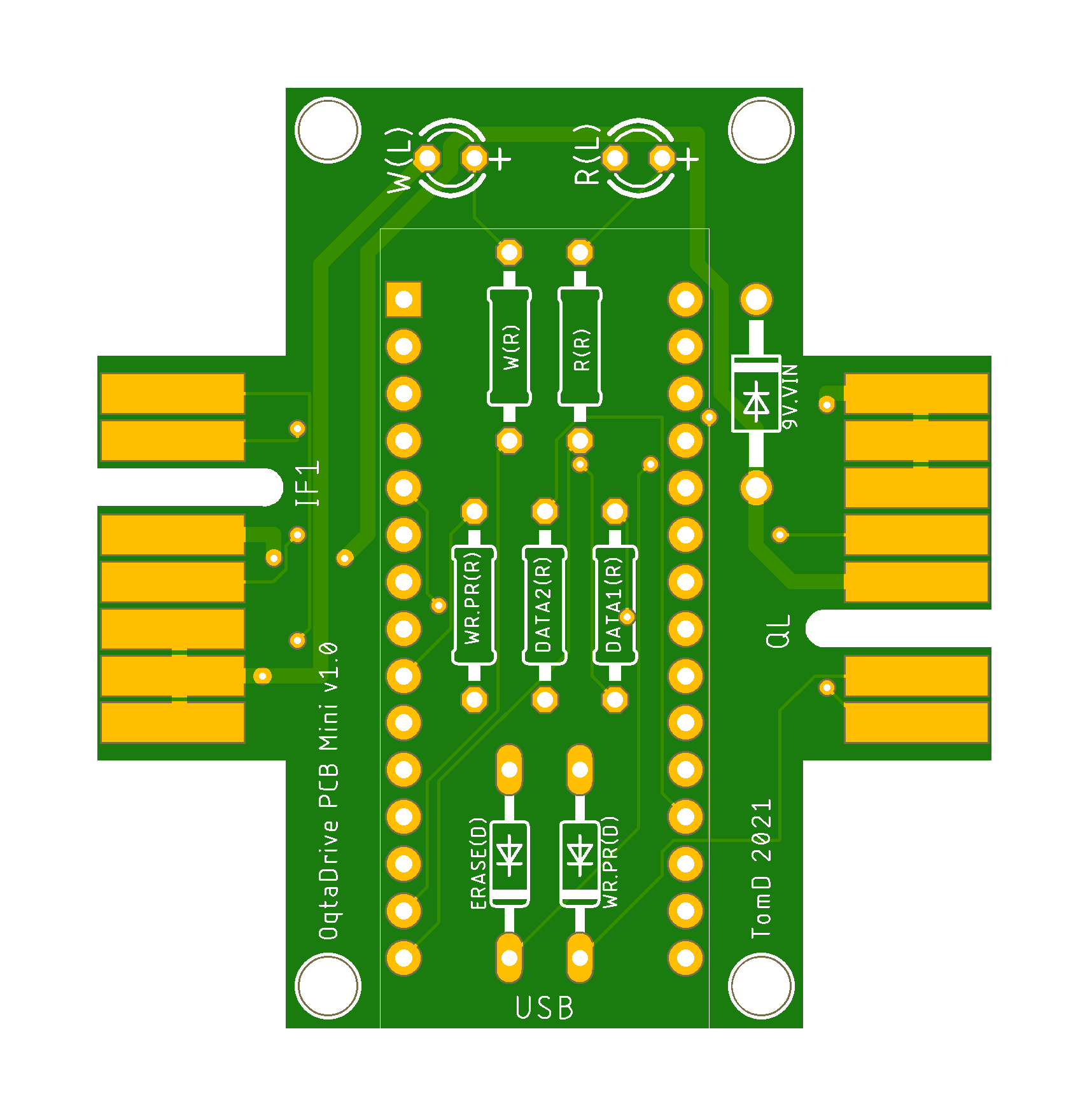
Deprecated - Lite & Mini
These two PCBs were early prototypes created by Tom. They are included here for completeness, to show the evolution of PCB development. Please consider building one of the more recent versions above.
The Lite and Mini are a little larger than the Micro, and have two edge connectors, one for Spectrum and one for QL. This has the advantage that the rear of the unit with the USB connector will always point to the back when you connect to either one. That’s because an Interface 1 has its edge connector on the left hand side, the QL on the right hand side. The rumble motor is not supported on these PCBs, as they were created before that feature was added. Otherwise, there’s no difference with the Micro.
🔗
|
🔗
|
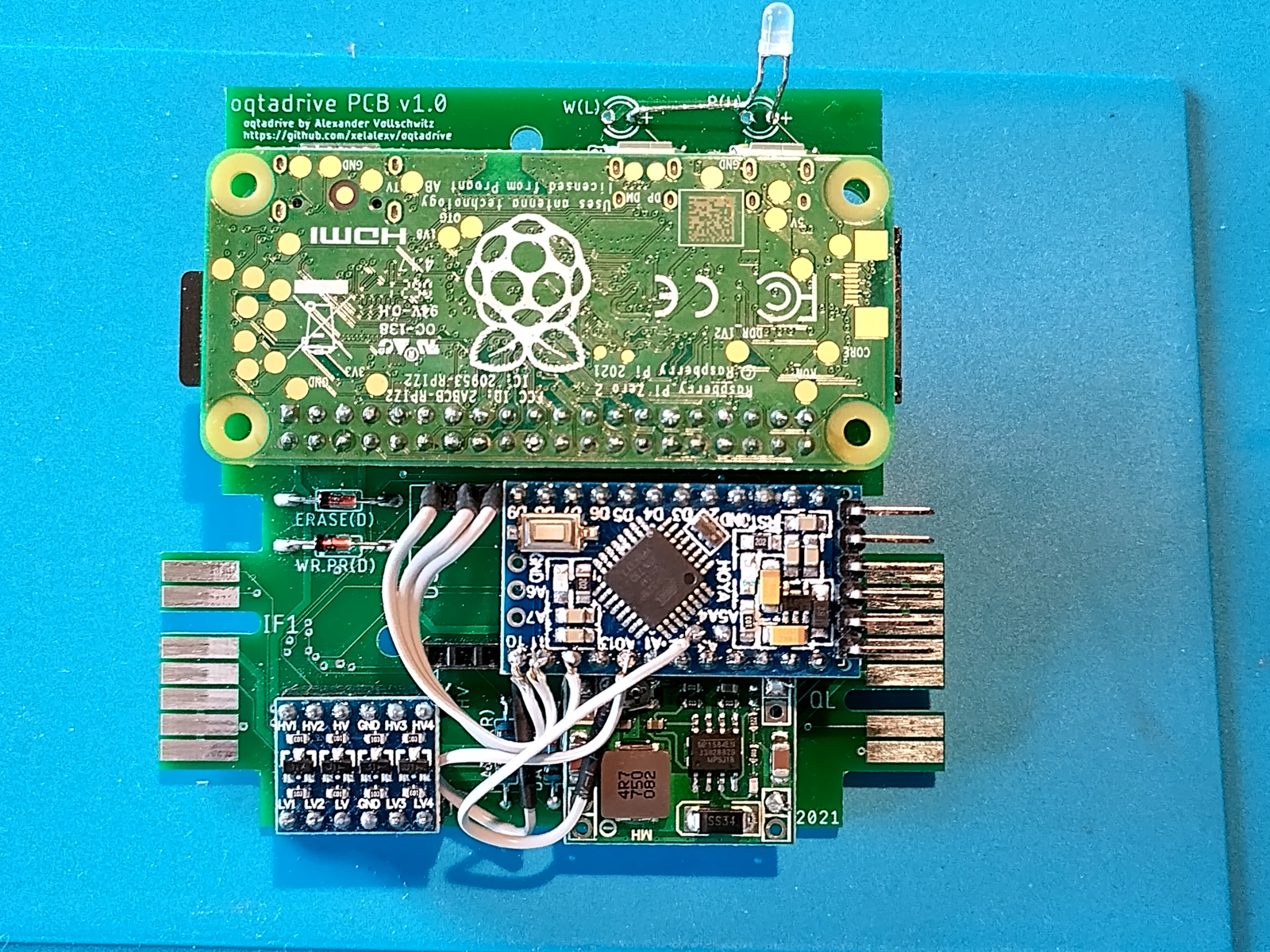
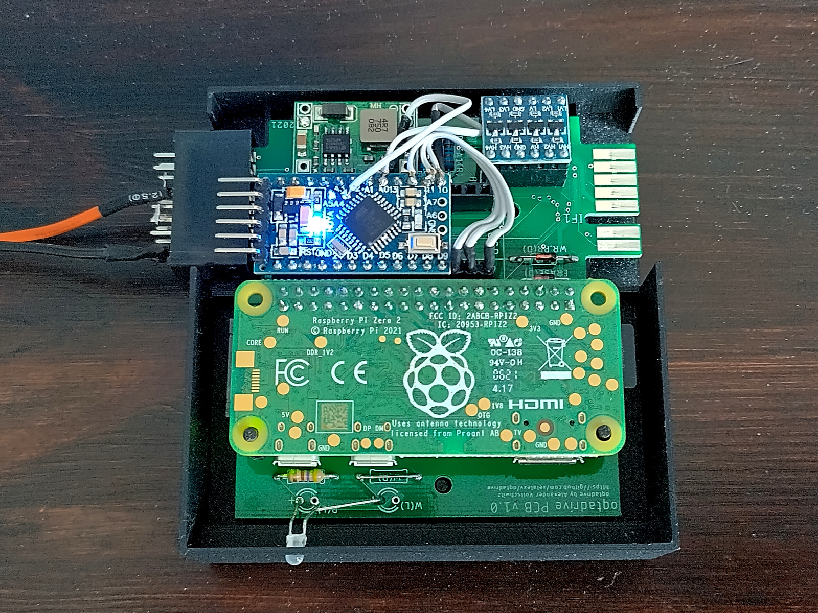
Using an Arduino Pro Mini
Since in the standalone configuration, the USB port of the Arduino Nano is not needed, it’s also possible to use an Arduino Pro Mini instead, which comes without the USB port. It’s important to note the different pin out though. It’s not a drop-in replacement! A few patch wires however are enough to fix this (pins D10, D11, D12, A0, and A4). In below example, the D10 and A0 pins of the Pro Mini were not fitted, since they would otherwise connect with the wrong signals on the PCB (A0 and A4) and block the patch wires. Software-wise the Pro Mini is fully compatible.
 |
 |
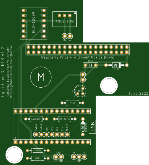
QL Add On
This PCB is installed into the case of the QL, the right choice if you want OqtaDrive permanently available in your QL. It replaces drive 1, but drive 2 can still be used and freely assigned to any drive number, or turned off. Tom also designed a 3D printed mounting bracket for the installation.
🔗
|
🔗
|
Other Options
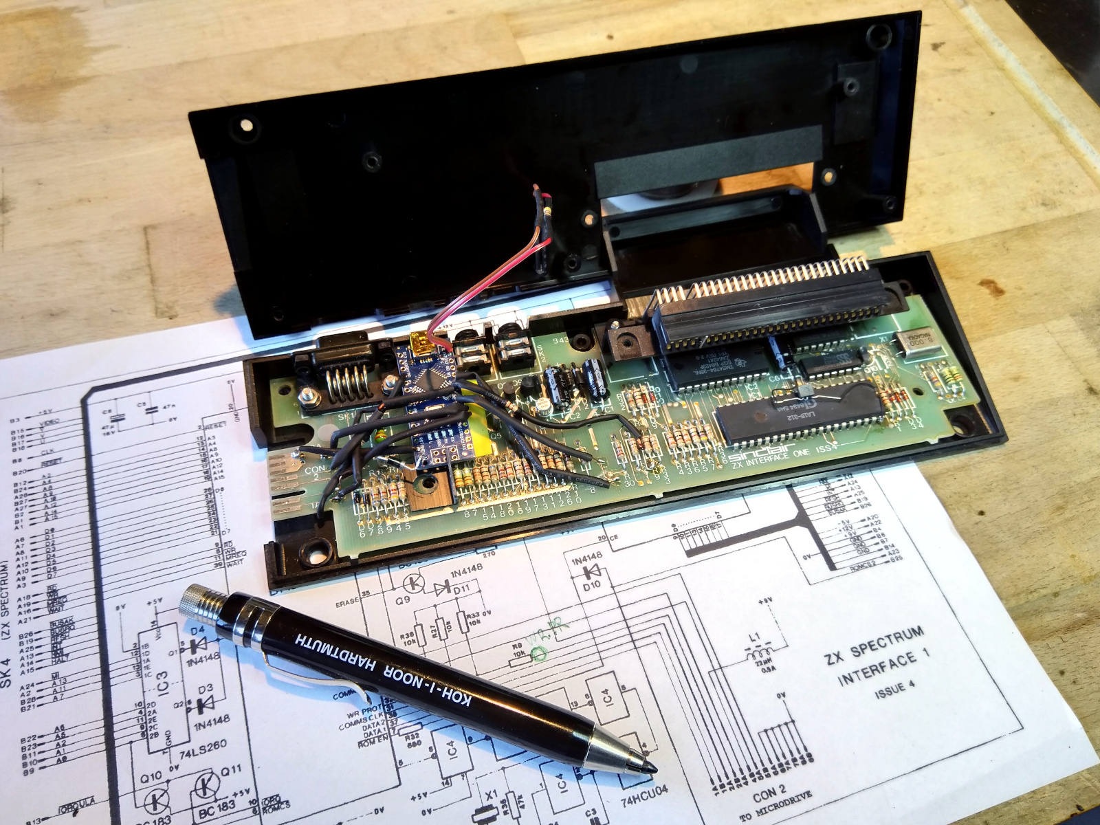
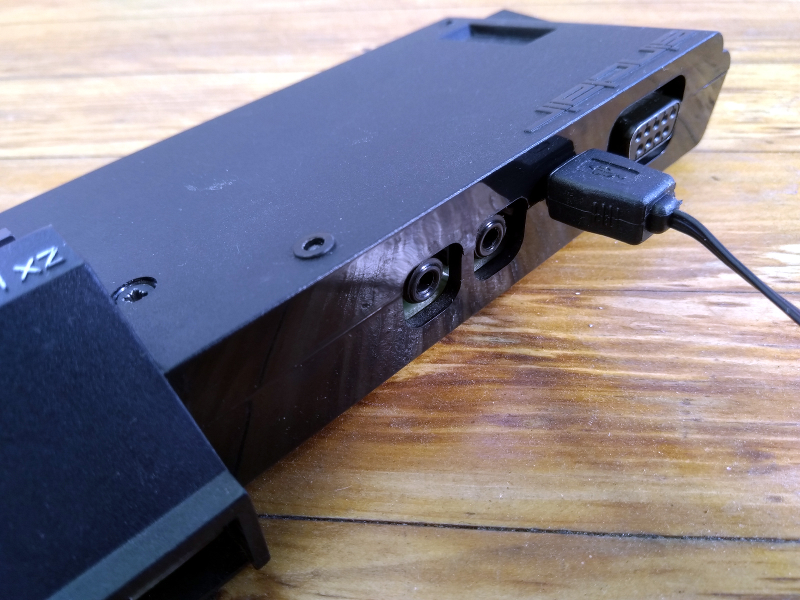
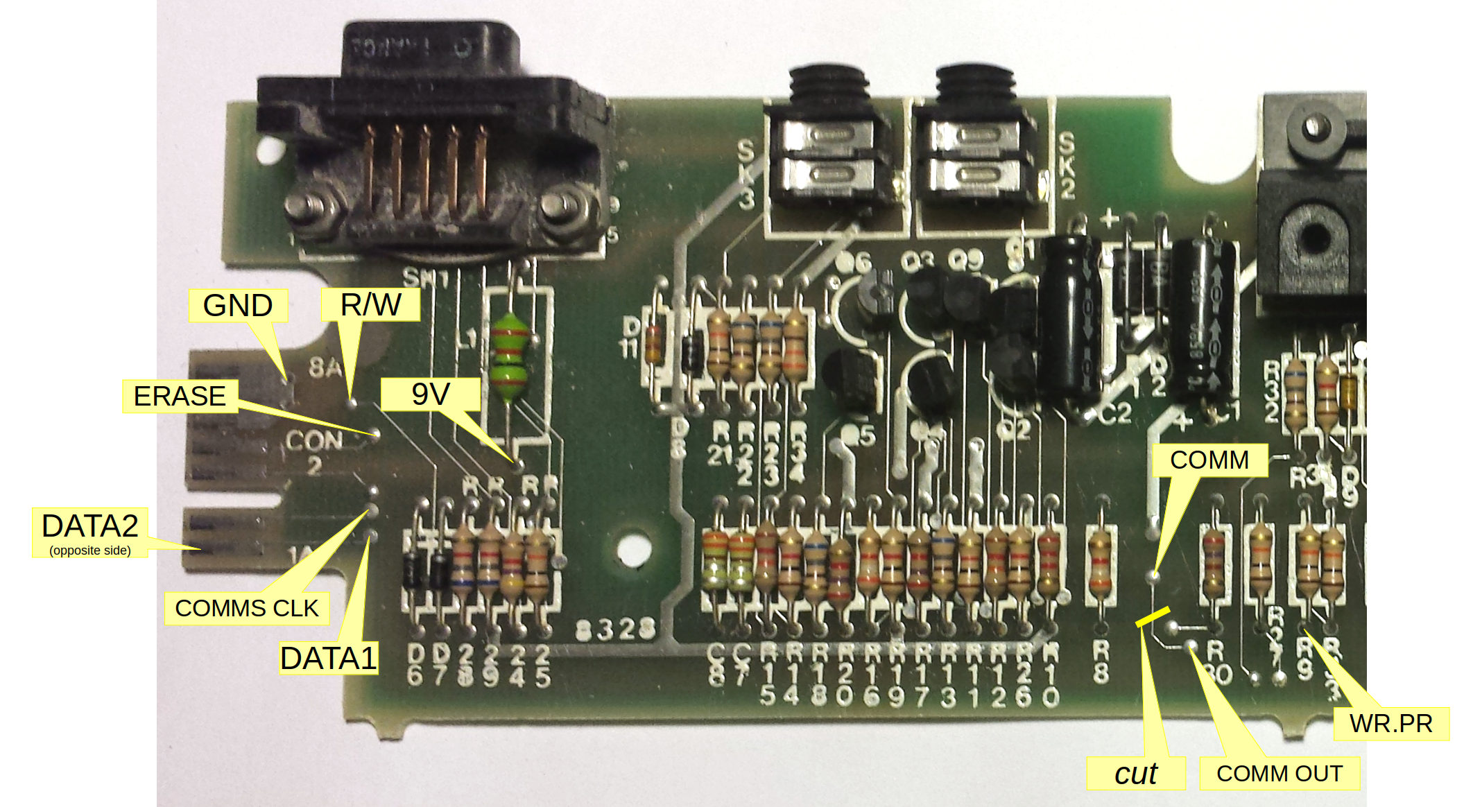
Inside Interface 1
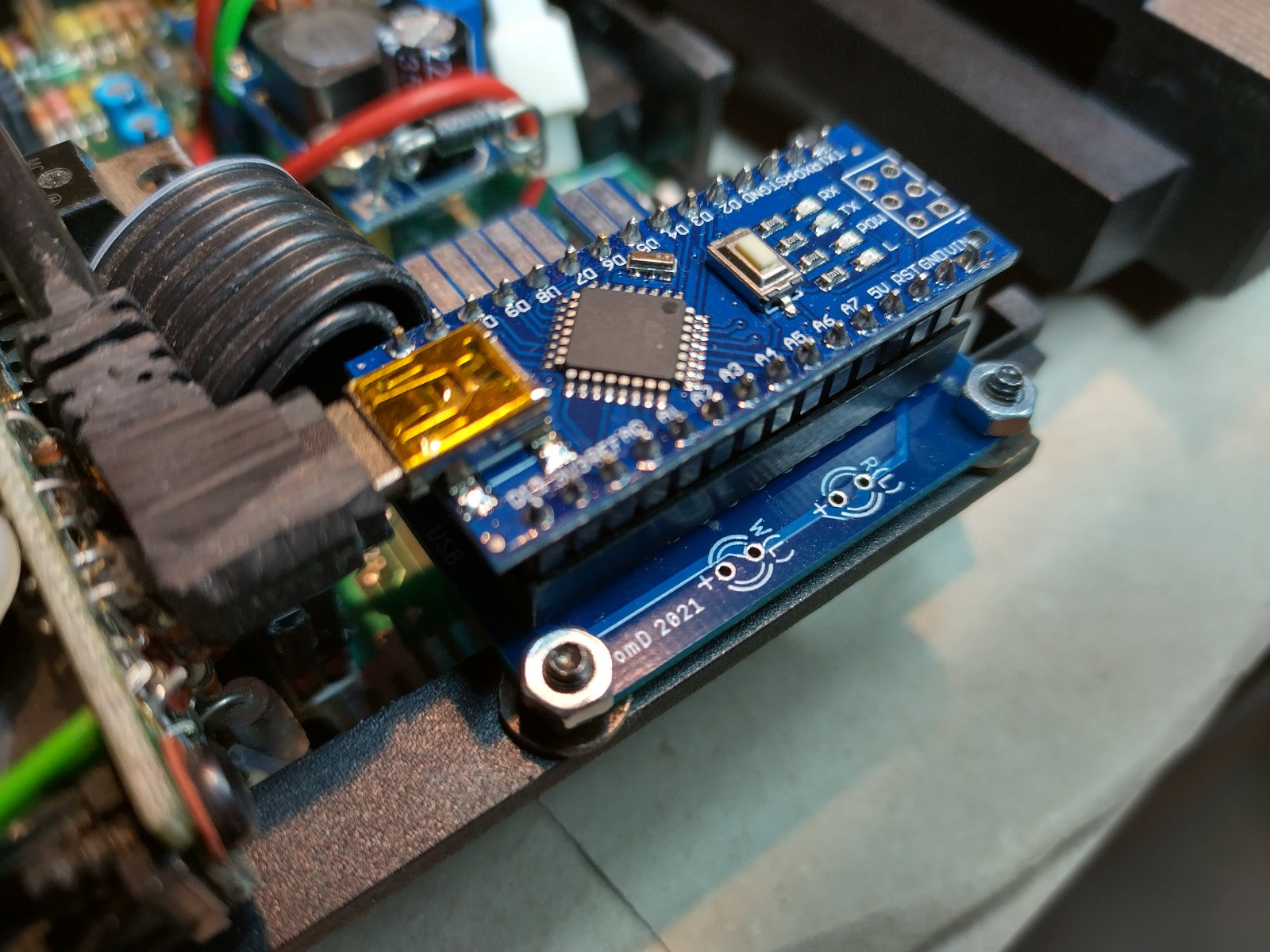
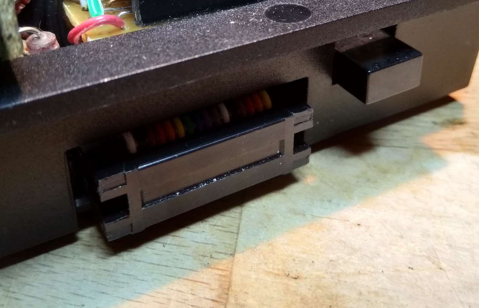
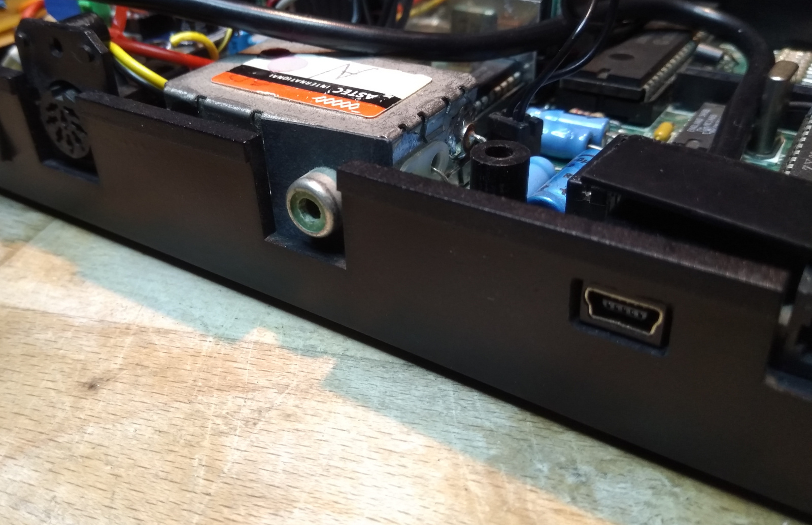
I personally also installed an OqtaDrive adapter into an Interface 1, hand-wiring the necessary connections. The Arduino Nano fits nicely between the serial port and network connectors.
 |
 |
 |
|
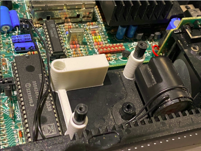
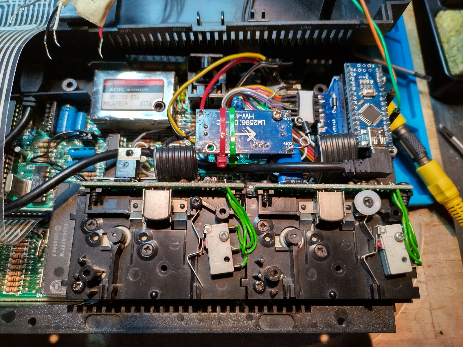
Inside QL (Adapter Only)
As a kind of light version of Tom’s QL add on described above, you can also install only the adapter into the QL. Here I used Tom’s Micro PCB, and kept both hardware drives. The adapter still hooks up to the external Microdrive port, except for the COMMS signal, which is directly taken from the PCB connector of internal drive 1 (pin 1). Drive 1 then gets COMMS from COMMS_OUT of the OqtaDrive adapter, i.e. the OqtaDrive adapter is now first in chain. A prerequisite for this build though is to replace the original 5V linear power regulator and its massive heat sink with a small bucket converter, to free up enough space.
 |
 |
 |
 |
Linino One
The Linino One is an interesting board in the Arduino family. It combines an ATmega32U4 micro-controller with an Atheros AR9331 System-on-a-Chip, giving you the real time capabilities we know from other Arduino boards, along with a Linux system for connectivity. Even though it was discontinued years ago, it’s still an interesting option, since it can be used as a standalone setup in itself. So no need for a RaspberryPi or BananaPi. You may be able to get a second hand or even a NOS board at a reasonable price. Just make sure it comes with the SD card add-on. But before you decide for the Linino, read up on the details, including drawbacks.
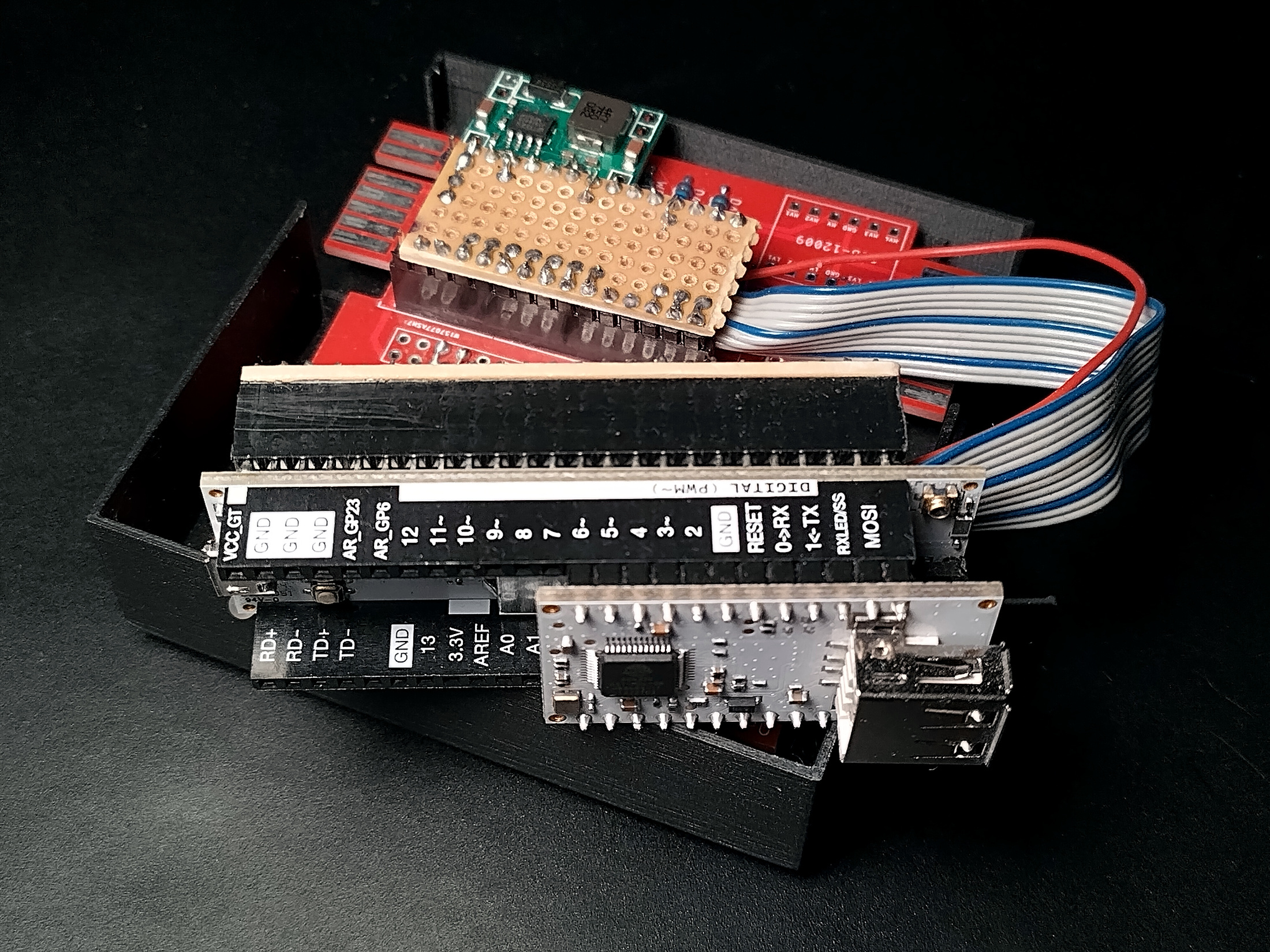
There’s currently no PCB available for the Linino One. For implementing support of this board, I fabricated an adapter cable that plugs the Linino into the Arduino Nano socket of a standalone PCB (pin mapping). In this case, you can skip the headers for the RaspberryPi and also the level converter, since they are not needed.